


How to Test a PCB Power Rail with a DC Power Supply: A Practical Troubleshooting Guide
How to Test a PCB Power Rail with a DC Power Supply: A Practical Troubleshooting Guide
When a PCB does not power on, resets unexpectedly, draws too much current, or becomes unusually hot, the problem may be related to its power rail.
A DC power supply is one of the most useful tools for checking PCB power rails because it allows engineers and repair technicians to control the input voltage, limit current, and monitor real-time current consumption.
Instead of immediately replacing components, you can use a controlled power source to determine whether the PCB is receiving the correct voltage, drawing normal current, or showing signs of a short circuit or power rail fault.
In this guide, we will explain how to test a PCB power rail with a DC power supply, what readings to look for, and how to troubleshoot abnormal current and voltage behavior.
What Is a PCB Power Rail?
A PCB power rail is a voltage supply path that distributes electrical power to different circuits or components on a printed circuit board.
Common PCB power rails include:
- 12V rail – commonly used for motors, relays, drivers, and power circuits
- 5V rail – commonly used for USB circuits, sensors, logic circuits, and development boards
- 3.3V rail – widely used by MCUs, communication ICs, sensors, and digital circuits
- 1.8V rail – often used by modern processors, memory, and low-voltage digital ICs
A PCB may contain several power rails generated from a single input.
For example:
12V Input → 5V Regulator → 3.3V Regulator → MCU
If one of these rails is missing, overloaded, or shorted, the entire PCB may fail to operate correctly.
This is why PCB power rail testing is an important step in electronics troubleshooting.
What Do You Need to Test a PCB Power Rail?
A basic PCB troubleshooting setup usually requires:
- Adjustable DC power supply
- Digital multimeter
- Test leads
- PCB under test
- Schematic or board documentation, if available
An oscilloscope can also be useful when you need to investigate ripple, noise, startup behavior, or fast voltage fluctuations.
For basic power-rail troubleshooting, however, an adjustable DC bench power supply and multimeter are often enough to identify many common problems.
Step 1: Check the PCB's Required Voltage
Before connecting the PCB to the power supply, determine its rated input voltage.
Check:
- PCB markings
- Product documentation
- Schematic
- Datasheet
- Input connector label
For example, if a PCB is designed for 5V input, do not start testing it at 12V simply because the power supply can provide 12V.
Set the DC power supply to the PCB's required voltage before connecting the output.
Example
For a 5V PCB:
Voltage setting: 5.00V
For a 12V PCB:
Voltage setting: 12.00V
The goal is to reproduce the PCB's normal operating power conditions in a controlled way.
Step 2: Set a Conservative Current Limit
One of the biggest advantages of using a laboratory DC power supply for PCB repair is the ability to set a current limit.
Do not immediately set the current limit to the maximum available current.
Instead, start with a conservative value based on the expected consumption of the PCB.
For example:
| PCB Type | Example Starting Current Limit |
|---|---|
| Small sensor board | 100–300mA |
| MCU development board | 300–1000mA |
| Small electronic module | 500mA–1A |
| Larger control board | 1–3A |
These are only starting examples. Always use the actual specifications of the PCB when available.
A lower initial current limit can provide an additional layer of protection during troubleshooting.
Step 3: Turn the Output OFF Before Connecting
Before connecting the PCB:
- Set the correct voltage.
- Set a conservative current limit.
- Verify positive and negative polarity.
- Connect the test leads.
- Connect the PCB.
- Turn the output ON.
Using the output switch on a bench power supply makes this process more convenient.
For example, the KUAIQU SPPS-Q Series provides an output ON/OFF control function together with adjustable voltage and current settings, making it suitable for controlled electronics testing.
Step 4: Observe the Current Draw
Once the PCB is powered, do not look only at the voltage.
Current consumption is one of the most useful clues when troubleshooting a PCB.
Observe the current shown on the DC power supply.
Different current behaviors can indicate different conditions.
| Observed Behavior | Possible Cause |
| Almost 0A | Open circuit, disconnected power path, or PCB not starting |
| Stable low current | PCB may be operating normally |
| Higher-than-expected current | Possible faulty component or excessive load |
| Current immediately reaches the limit | Possible short circuit or severe overload |
| Current fluctuates repeatedly | Startup problem, unstable circuit, or intermittent fault |
| Current suddenly increases | Component failure or power rail problem |
The actual expected current depends heavily on the PCB design, so these observations should always be compared with the board's specifications.
Step 5: Check Whether the Power Supply Enters CC Mode
If the PCB attempts to draw more current than the configured current limit, the power supply may enter Constant Current (CC) mode.
For example:
- Set voltage: 5V
- Current limit: 1A
- PCB attempts to draw: 2A
The power supply limits the current to approximately the configured level.
As a result, the output voltage may fall below the original 5V setting.
This is an important troubleshooting clue.
Example
You set:
5.00V / 1.00A
After connecting the PCB, you observe:
3.2V / 1.0A
This could indicate that the PCB is attempting to draw more current than the configured limit.
Possible causes include:
- Short circuit
- Damaged IC
- Failed capacitor
- Incorrect component installation
- Faulty voltage regulator
- Excessive load
Do not automatically increase the current limit just because the voltage has dropped. First investigate why the PCB is demanding excessive current.
Step 6: Check the PCB Power Rail with a Multimeter
The DC power supply tells you how much power is being delivered to the board.
A multimeter can help you determine what voltage actually reaches different points on the PCB.
For example, if the PCB input is 5V, measure:
Input → Regulator → Output Rail
You may find:
5.00V input → 5.00V regulator input → 3.30V regulator output
If the input is correct but a downstream rail is missing, the problem may be located around the regulator or its associated components.
Step 7: Test 5V and 3.3V Power Rails
Many modern electronic boards contain both 5V and 3.3V power rails.
Testing a 5V Rail
A 5V rail is commonly found in:
- USB circuits
- Development boards
- Sensors
- Relay circuits
- Logic circuits
Check whether the rail is close to its expected voltage under normal operating conditions.
Testing a 3.3V Rail
A 3.3V rail is commonly used by:
- Microcontrollers
- Wireless modules
- Sensors
- Memory
- Digital ICs
If a 3.3V rail is missing while the upstream voltage is correct, investigate the voltage regulator, converter, enable signal, or possible short circuit on the 3.3V rail.
How to Find a Short Circuit on a PCB with a DC Power Supply
A DC power supply can also help identify suspected short circuits.
Suppose you connect a 5V PCB and observe:
5V → Current immediately reaches the limit → Voltage drops
This is a strong indication that the PCB may have an abnormal load.
A Basic Troubleshooting Procedure
1. Disconnect the PCB
Turn the output OFF before changing connections.
2. Check the board visually
Look for:
- Burn marks
- Damaged ICs
- Solder bridges
- Incorrect components
- Damaged capacitors
- Loose or incorrectly installed parts
3. Check resistance with the power OFF
Use a multimeter to measure resistance between the suspected power rail and ground.
4. Reconnect the board with a controlled current limit
Use the PCB's rated voltage but keep the current limit conservative.
5. Observe current consumption
If the power supply immediately reaches the current limit, investigate the affected power rail.
6. Locate the abnormal component
Depending on the circuit, excessive current may cause a faulty component to heat up.
A thermal camera can also be useful for locating abnormal heating.
Do Not Increase the Current Limit Just Because the Voltage Drops
This is one of the most important rules when using a bench power supply for PCB repair.
If the voltage falls because the PCB is drawing excessive current, simply increasing the current limit can make the situation worse.
For example:
Initial setting:
5V / 1A
Observed:
3V / 1A
Increasing the current limit to 5A may allow significantly more current to flow through a faulty component or short circuit.
Instead, determine why the board is demanding excessive current first.
Current limiting is not only a measurement function—it can also be an important protection tool during PCB troubleshooting.
How to Test a PCB Power Rail Safely
Follow these basic practices when powering an unknown or potentially damaged PCB:
1. Verify Polarity
Make sure positive and negative connections are correct.
2. Start with the Rated Voltage
Do not exceed the PCB's specified input voltage.
3. Use a Conservative Current Limit
Especially when testing an unknown or repaired board.
4. Monitor Current Immediately After Power-On
A sudden current spike can provide important information about the circuit.
5. Use OCP When Available
Over Current Protection can provide additional protection during abnormal conditions.
6. Turn the Output OFF Before Changing Connections
This reduces the risk of accidental shorts or incorrect connections.
7. Do Not Ignore Unusual Heating
Abnormal current and localized heating can indicate a damaged component or shorted power rail.
What Does Different Current Consumption Tell You?
Current consumption can provide a quick picture of PCB behavior.
Near-Zero Current
Possible causes:
- No power path
- Broken connector
- Open circuit
- Power switch disabled
- Faulty input protection
Normal Current
The board may be operating normally, although further functional testing may still be required.
Excessive Current
Possible causes:
- Short circuit
- Damaged IC
- Failed capacitor
- Faulty regulator
- Incorrect component
- PCB contamination
Pulsing Current
Possible causes:
- Repeated startup attempts
- Protection circuit activation
- Regulator instability
- MCU boot problems
- Intermittent fault
Current behavior should always be interpreted together with the PCB schematic and expected operating conditions.
Choosing a DC Power Supply for PCB Testing
For PCB repair and troubleshooting, a useful DC power supply for PCB testing should provide more than adjustable voltage.
Important features include:
Adjustable Voltage and Current
Allows you to match the power supply to different PCB requirements.
Real-Time Current Display
Makes abnormal current consumption easier to identify.
Current Limiting
Helps prevent excessive current from flowing into a faulty board.
OVP and OCP Protection
Provides additional protection during testing.
Output ON/OFF Control
Allows the engineer to safely start and stop power delivery.
Clear Digital Display
Makes voltage and current easier to monitor during troubleshooting.
For more advanced PCB development, higher-resolution current measurement can also be useful when investigating low-power circuits, standby consumption, and leakage.
For example, the KUAIQU SPPS-K Series offers high-resolution voltage/current measurement and is positioned for electronics repair, circuit debugging, and precise testing.
Recommended KUAIQU DC Power Supplies for PCB Testing
Different PCB testing tasks may require different power supply capabilities.
For General PCB Repair
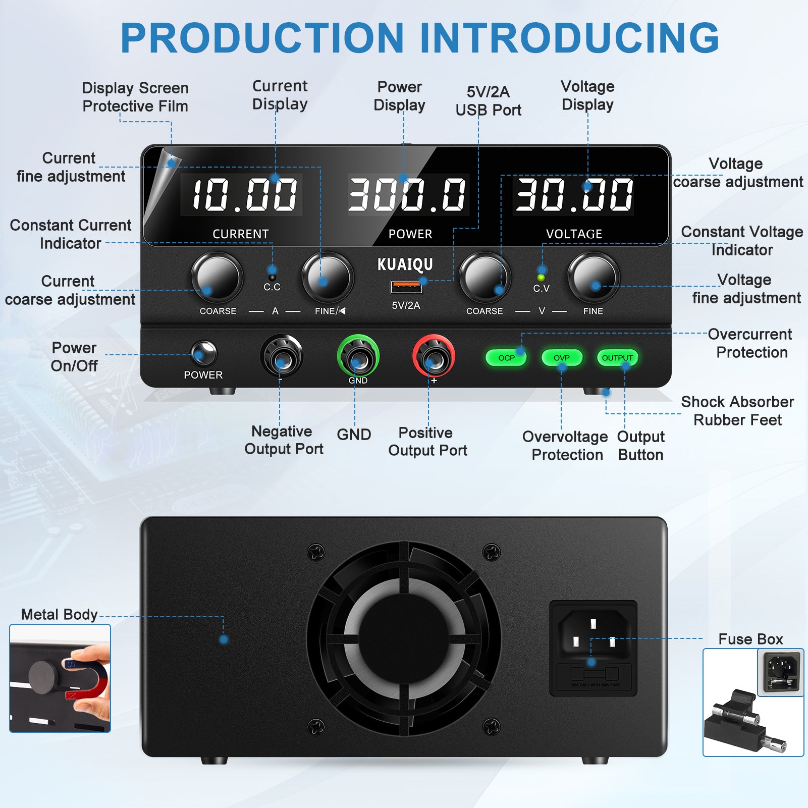
The KUAIQU SPPS-H305 provides 0–30V and 0–5A adjustable output and is specifically positioned for PCB repair, electronics troubleshooting, component testing, and circuit development.
For Modern Electronics Workbenches
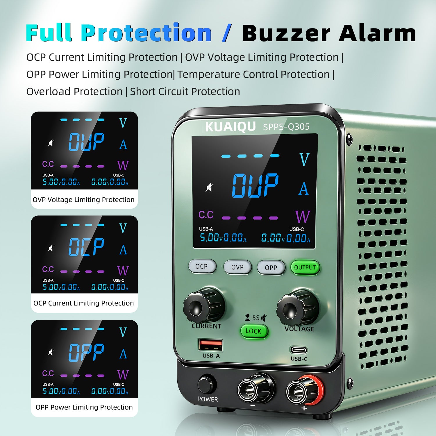
The KUAIQU SPPS-Q Series adds a color LCD interface, adjustable DC output, real-time measurements, and integrated protection functions, making it suitable for everyday electronics testing and repair.
Explore the KUAIQU SPPS-Q Series
For Precision PCB and Low-Current Testing
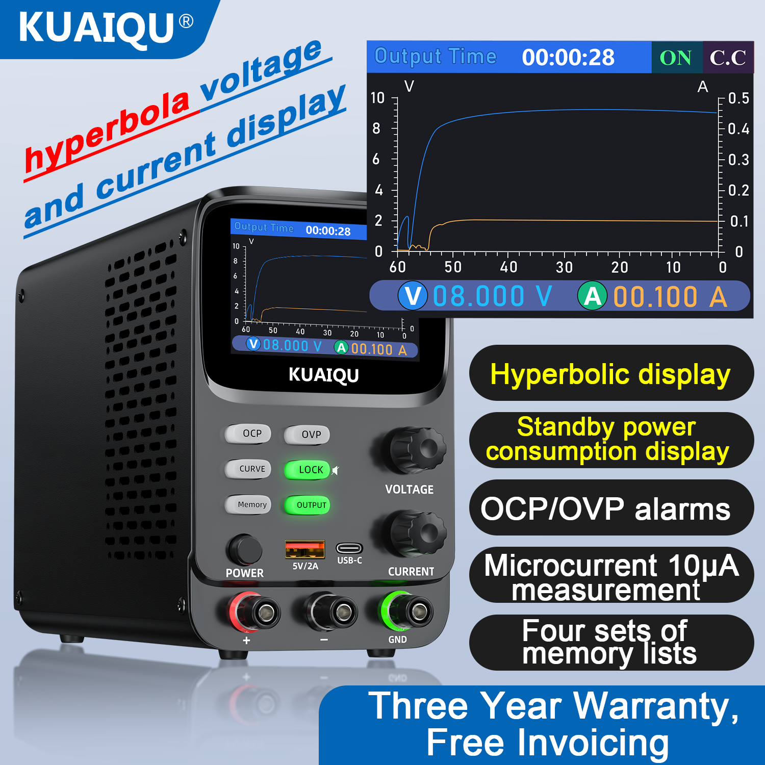
The KUAIQU SPPS-K Series provides high-resolution voltage and current measurement and real-time output curve monitoring. It is particularly useful when engineers need to observe small current changes during circuit debugging and electronics testing.
Explore the KUAIQU SPPS-K Series
Common PCB Power Rail Testing Mistakes
Avoid these common mistakes when using a DC power supply for PCB troubleshooting.
Mistake 1: Setting the Maximum Current Immediately
A higher current limit does not mean the PCB will operate better.
Set the current limit according to the expected load.
Mistake 2: Ignoring Current Consumption
A PCB can show the correct voltage while drawing abnormal current.
Always monitor both voltage and current.
Mistake 3: Increasing Voltage to Fix a Voltage Drop
If the voltage drops because of excessive current demand, increasing the voltage may damage the board.
Investigate the load first.
Mistake 4: Connecting Power with the Output Enabled
Accidental shorts can occur during connection.
Turn the output OFF before connecting or disconnecting the PCB.
Mistake 5: Assuming Every Low-Resistance Rail Is a Short
Some modern circuits naturally have relatively low resistance on certain power rails.
Resistance measurements should be interpreted according to the circuit design and component characteristics.
Final Checklist: Testing a PCB Power Rail
Before powering the board, check:
- PCB rated input voltage
- Correct polarity
- Appropriate current limit
- Output OFF during connection
- Test leads securely connected
After powering the board, monitor:
- Output voltage
- Load current
- Whether the power supply enters CC mode
- Abnormal current spikes
- Voltage stability
- Component temperature
- Downstream power rails
A controlled DC power supply for PCB testing allows engineers to turn power consumption into useful diagnostic information.
Instead of simply asking whether a PCB turns on, you can observe how much current it draws, whether the voltage remains stable, and whether a particular power rail behaves normally.
For PCB repair, prototype validation, and electronics troubleshooting, these measurements can significantly narrow down the possible causes of a fault.
Looking for a reliable adjustable DC power supply for PCB testing and electronics repair? Explore the KUAIQU range of bench power supplies for different voltage, current, and precision requirements.